Tech Note – Limiting Power Draw on SV Series Controllers
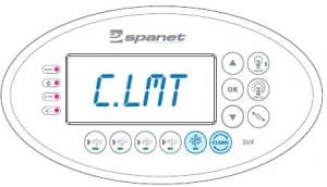
The power draw by the SV controllers can be limited or increased to suit the electrical supply to the spa. The Electric element, Heat pumps and water pumps all require different settings to be adjusted to control their operation. All these settings are accessed by entering the hidden OEM menu by simultaneously pressing and holding: Air Blower & W.CLN buttons together until [C.LMT] appears on the display as per FIG 1.
| SV2-T | SV3-T | SV4-T |
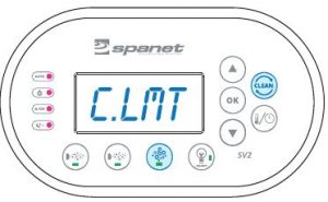 |
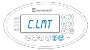
Figure 1 |
 |
Once in the menu, a ten (10) second idle menu time out period exists. If a button press is not detected for 10 seconds the menu will time out and the screen will return to the default display mode.
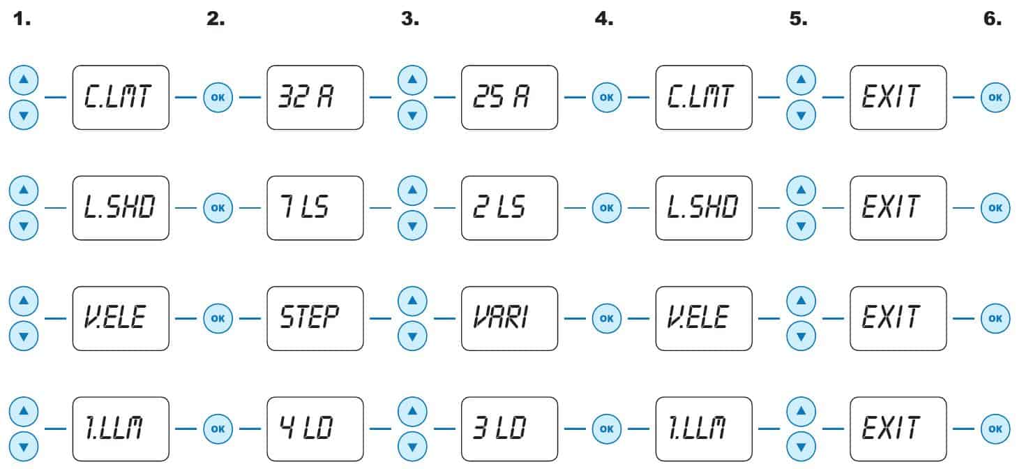
1. To change these settings use the UP & DOWN buttons to navigate the configuration menu.
2. Press OK to enter the desired settings menu.
3. Use the UP or DOWN buttons to adjust the setting to the desired value.
4. Press OK to confirm and save new setting. The current menu will be displayed on the screen.
5. Once the required changes have been completed, navigate the menu by pressing either the UP or DOWN button
until the display shows [EXIT]
6. Press OK button to exit the menu and return to the default display.
Electrical Wiring (Terminal Block Connections)
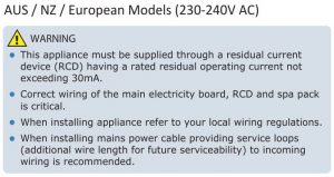
The SV controller is supplied with a multi-phase terminal block capable of connecting to a single, dual or three phase
power supply. When shipped the controller is configured for a single phase power connection. Removing the
appropriate terminal block linking wires and adjusting the DIP Switches, the controller is ready for connection of either
a dual or three phase power supply. This Multi-Phase ability is particularly useful when the circuit has a limited
availability of current per phase.
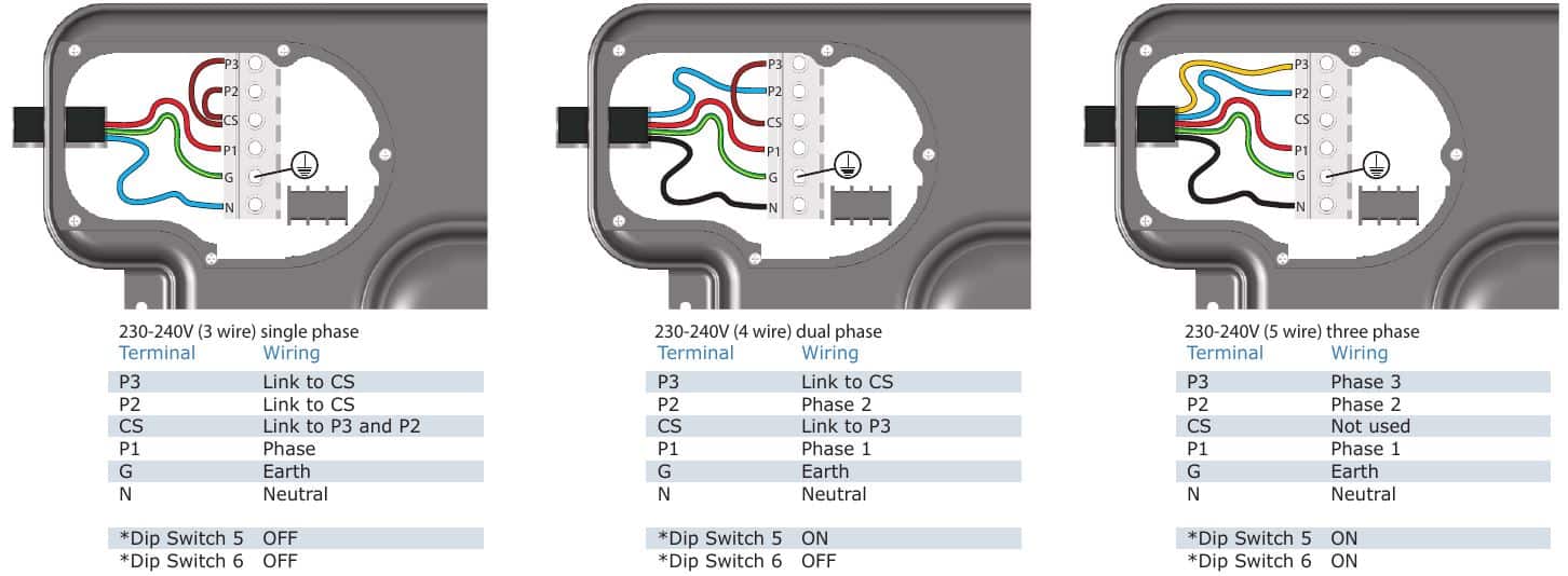
Figure 2
⇒ In single phase applications the outlet sockets are still governed by the fuse/current limit of each phase. The power outlet arrangement is as follows:
| PHASE 1 | PHASE 2 | PHASE 3 |
| circulation pump | pump 1 | pump3 |
| sanitiser (ozone/uv) | pump 2 | pump4 |
| blower heater# | mains* | mains* |
* Dedicated 230-240V power outlets (always on)
# Heater is connected internally to phase 1. Consider when calculating total current draw of phase 1
C.LMT (current limit)
Governing the controller’s power draw from the electric element
Every SV controller features a variable heater so the amount of power supplied to the heater can be adjusted. The Controller will automatically adjust the heater size (kW) so it will maximise the heater output while maintaining the power draw within the limits of the circuit breaker.
PLEASE NOTE: The C.LMT (current limit) setting ONLY effects the power draw from the heater.
The C.LMT does not govern or restrict the amount of power that a heat pump, water pumps or blower use or take into account power being drawn through separate phases that are not linked to the first phase.
The installer should adjust the C.LMT setting to match the rating of the circuit breaker feeding the spa.
L.SHD (Load Shed Count)
The C.LMT does not control external heat pump operation.
This setting should be used if an external heat pump is installed
The Load Shed determines the number of loads that can be engaged before heating is turned off. Each devices running current should be subtracted from the available current to the spa starting with the heat pump followed by the largest to smallest loads when calculating the load shed count.
The filtration pump is not counted as a load, the blower and all other pumps are.
Example:
Load Shed Count = 2
When the 2nd loads in addition to the filtration pump is turned ON, the heater load sheds and turns OFF.
The L.SHD setting ranges from 1 to 7.
1 = maximum load shed
7 = load shed disabled (default)
* The circulation pump is the filtration pump and is therefore NOT considered a load and will NOT be governed by the L.SHD
(load shed) setting, HOWEVER you must take into account its power draw when calculating how much power the jet pumps and
blower will use. The circ pump will ALWAYS run if the heat pump is operating.
V.ELE (Variable Element Operation)
Control of electric element operation
Variable element operation allows the SV controller to automatically adjust the heater power level to the available current when devices (ie pumps and/or blower) are operating.
The setting choices are:
STEP – (default) Controller will choose which element can be turned on without exceeding current limit.
This setting allows for faster activation of the element
VARI – Controller will gradually ramp the heater up to maximise heater output.
OFF – Variable element disabled. (C.LMT will be ignored, L.SHD settings nay need to be configured to ensure the controller does not exceed its maximum current limit.
1.LLM (load limit)
How to govern number of loads that operate at once
Pump or blower motors are a certain size and must maintain a certain RPM, so their current draw is fixed and cannot be adjusted. If the available current (amps) for a spa circuit is limited, the installer must consider how much current (amps) each jet pump and/or blower will use and where required
must adjust the 1.LLM (load limit) setting to restrict the number of loads that operate at the one time, to keep the total power draw of the spa within the circuit breaker limits.
Each jet pump and blower is considered a load. The filtration pump is NOT considered a load. The load limit setting (1.LLM) governs how many loads can be turned on at the same time. (i.e. If 1.LLM= 2, only two loads can operate simultaneously. E.g. 2 x jet pumps could be operated together OR 1 x jet
pump and 1 x blower, but if you tried to turn on 3 x jet pumps or 2 x jet pumps + blower, the third device would NOT be allowed to turn on to keep the power draw to a certain limit. One jet pump or blower would have to be turned off before the other load could be turned on).
A rough guide of the power (amp) draw for equipment running on a spa pool is as follows:
| MODEL | DESCRIPTION | AMPS |
| XS-3C or SC05 | 250W circulation pump | 1.3A* |
| XS-10B or SA10 | 700W air blower | 3.3A |
| XS-30 or SB25 | 1850W jet pump | 8.1A |
| XS-30S or SB30 | 2200W jet pump | 9.6A |
* The circulation pump is the filtration pump and is therefore NOT considered a load and will NOT be governed by the 1.LLM (load limit) setting, HOWEVER you must take into account its power draw when calculating how much power the jet pumps and blower will use. The circ pump will ALWAYS run if a jet pump is operating.
If a controller is connected to a multi phase power supply and the DIP switches are set accordingly, the load limit can be adjusted per phase
Dual Phase
1.LLM – Governs the blower and Pumps on the linked phase
2.LLM – Governs Phase 2
3 Phase
1.LLM – Governs the Blower
2.LLM – Governs Pump 1 & 2 on the 2nd phase
3.LLM – Governs Pump 3 & 4 on the 3rdd phase


